Views: 0 Author: Site Editor Publish Time: 2026-05-14 Origin: Site


Industrial component degradation creates high-stakes challenges across heavy manufacturing sectors. Equipment downtime, steep replacement parts pricing, and sudden safety hazards severely threaten operational stability. Selecting the incorrect coating method directly accelerates these component failures. A mismatched approach quickly leads to premature coating spallation, aggressive galvanic corrosion, or sudden thermal fatigue. The wrong choice damages base materials and ruins critical machinery.
This article provides an engineering-led, evidence-based framework to solve this ongoing issue. You will discover how to precisely match operational environments to the correct application techniques, material properties, and vendor capabilities. We outline clear steps to evaluate geometrical constraints and establish rigorous performance metrics. By following this guide, you can confidently specify highly durable coatings designed for your exact industrial applications.
No single thermal spray process fits all environments; selection depends on a strict balance of porosity, bond strength, and substrate compatibility.
High-Velocity Oxygen Fuel (HVOF) provides the highest density and bond strength for severe wear, while Plasma Spray excels in extreme heat (Thermal Barrier Coatings).
Evaluating geometrical constraints, masking requirements, and thermal limitations of the base material is just as critical as selecting the coating material.
Partnering with vendors who can deliver certified Thermal Spray Customized Products ensures compliance with industry standards (e.g., ASM guidelines) and rigorous metallurgical QA.
Engineers often rush toward selecting a coating material before fully understanding the operational environment. You must establish a strict operational baseline first. This prevents misapplying a high-end coating to a low-stress environment or under-protecting a critical moving part.
You must isolate exactly how and why the component fails. Parts degrade differently depending on their operating conditions. Abrasive wear gouges surfaces when hard particles slide across them. Chemical corrosion dissolves metals via acidic or alkaline attacks. Thermal cycling expands and contracts metals, causing fatigue fractures over time. Sometimes, components suffer from hot corrosion, a brutal combination of extreme heat and chemical attack. Identifying the dominant failure mode immediately narrows down your coating options.
Every base material possesses thermal limitations. You must define the maximum temperature the base material can withstand before losing mechanical properties. Aluminum alloys, for example, warp or lose temper at relatively low temperatures compared to carbon steel. Heat generated during application can easily distort thin-walled geometries or alter the metallurgical grain structure of the substrate. Recognizing these limits dictates how much cooling is necessary during the application.
Vague goals like "make it last longer" lead to engineering failures. You need quantifiable baseline requirements to ensure success. Establish these parameters early:
Required bond strength: Measure this in MPa or psi. Severe wear environments demand bond strengths exceeding 10,000 psi to prevent delamination.
Maximum acceptable porosity percentage: Corrosion protection requires less than 1% porosity to stop liquids from penetrating to the base metal.
Required surface finish: Determine if the part functions as-sprayed or requires post-coating diamond grinding to achieve strict micro-inch tolerances.
Selecting the optimal thermal spray process requires understanding the balance between thermal energy and kinetic energy. Each method accelerates particles differently. The following matrix breaks down the core technologies available today.
Process Type | Energy Profile | Typical Porosity | Ideal Applications |
|---|---|---|---|
HVOF / HVAF | High Kinetic, Low Thermal | < 1% | Severe abrasion, sliding wear |
Atmospheric Plasma Spray | High Thermal, Moderate Kinetic | 2% - 5% | Thermal barriers, extreme heat |
Twin Wire Arc Spray | Moderate Thermal, Moderate Kinetic | 3% - 10% | Corrosion protection, restoration |
Combustion Flame Spray | Low Kinetic, Moderate Thermal | 10% - 15% | General repair, salvage |
HVOF relies on high kinetic energy and relatively low thermal energy. This mechanism shoots particles at supersonic speeds. The impact creates extremely dense coatings. HVOF boasts extremely low porosity, often below one percent. It delivers exceptionally high bond strength. This process is ideal for applying hard carbides, like tungsten or chromium. It excels in environments punishing components through severe abrasion, erosion, and sliding wear.
APS utilizes extreme thermal energy. The plasma plume can reach up to 16,000°C. Despite this intense heat, the kinetic energy remains moderate. This mechanism easily melts high-melting-point ceramics like zirconia and alumina. Because the heat dissipates rapidly in the air, APS applies these ceramics without altering the substrate metallurgy. APS stands as the premier choice for Thermal Barrier Coatings (TBCs), extreme heat resistance, and reliable electrical insulation.
Twin Wire Arc Spray uses electric arc melting combined with compressed air atomization. Two electrically charged wires meet, create an arc, and melt. Compressed air then blasts the molten droplets onto the substrate. This process delivers high deposition rates. It remains highly cost-effective and is easily applied in field environments. Engineers primarily use Arc Spray for large-scale corrosion protection, applying zinc or aluminum to infrastructure. It also works exceptionally well for dimensional restoration on worn shafts.
Flame spray utilizes a basic oxy-fuel flame to melt the feedstock. It offers low equipment costs and applies material slowly. This slower rate makes it good for complex geometries requiring moderate protection. While it lacks the dense bond strength of HVOF, Flame Spray remains highly effective for general low-stress corrosion protection. Machinists frequently use it for salvage and repair on non-critical bearing journals.
Once you understand the available technologies, you must map them to your specific environmental threats. Aligning the coating architecture to the exact degradation mechanism guarantees long-term operational success. Using Thermal Spray technologies effectively means matching the metallurgical properties of the coating to the physics of the operational environment.
Wear destroys components quickly. The primary requirement here is extreme hardness combined with high density. You must prevent abrasive particles from penetrating the surface. If a coating contains high porosity, hard abrasive grains will catch in those voids and rip the coating apart. The winning formula for severe wear involves using HVOF to apply Tungsten Carbide (WC-Co) or Chromium Carbide. The supersonic impact speeds tightly pack the carbide grains together. This creates an impenetrable armor ideal for pump impellers, hydraulic rods, and drilling equipment.
Corrosion demands an entirely different approach. The core requirement is achieving zero interconnected porosity. If microscopic channels exist within the coating, corrosive media will penetrate and reach the substrate. This triggers galvanic corrosion, bubbling the coating off from the inside out. The winning formula depends on the scale of the project. For localized, highly dense coatings, HVOF provides the best barrier. For large-area sacrificial protection, Arc Spray works best. Engineers often follow Arc Spray applications by applying specialized resin sealers to close any remaining surface voids completely.
Heat degrades structural integrity fast. Components operating inside gas turbines or combustion chambers require low thermal conductivity. They also demand high resistance to thermal shock. The base metal must remain much cooler than the operating environment. The winning formula here is Plasma Spray applied Yttria-Stabilized Zirconia (YSZ). Engineers apply this ceramic over a specialized metallic bond coat. The bond coat prevents high-temperature oxidation of the substrate, while the porous ceramic topcoat provides superior thermal insulation.
Great materials fail when applied to poorly designed geometries. You must accommodate the physical realities of the spraying equipment. Ignoring these design rules leads to inconsistent coverage, built-up residual stresses, and eventual coating delamination.
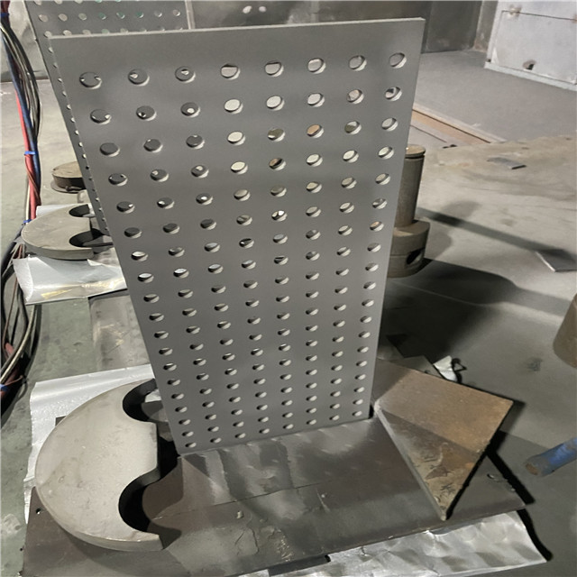
Particle deposition requires direct, optimized angles. The ideal spray angle sits between 45 and 90 degrees relative to the surface. If the angle drops below 45 degrees, particles bounce off instead of bonding. This creates a severe line of sight constraint. Coating deep internal diameters (IDs) or complex undercuts proves incredibly difficult. Specialized miniaturized spray guns exist for IDs, but they offer lower kinetic energy than standard external guns. You must design components allowing open access for the spray plume.
Sharp edges act as stress concentrators. When molten particles hit a sharp 90-degree corner, they shrink as they cool. This shrinkage causes immense stress build-up. The coating will eventually crack and spall off at these sharp edges. You must design parts utilizing chamfered or rounded edges (typically a minimum radius of 1.5mm). Additionally, consider the operational realities of masking non-coated areas. Masking materials must survive severe grit blasting and intense heat. Complicated masking requirements drastically increase production time and labor.
Engineers often hold the dangerous misconception regarding thickness. Thicker is rarely better. As coating thickness increases, residual stress accumulation multiplies rapidly. Different processes yield different optimal thickness ranges.
Plasma Sprayed Ceramics: Typically limited to 0.2mm - 0.5mm to prevent thermal cycling delamination.
HVOF Carbides: Usually optimized between 0.1mm - 0.3mm. Exceeding this often causes compressive stress fractures.
Arc Sprayed Metals: Can be applied much thicker (up to several millimeters) due to different stress profiles and higher porosity.
You must strictly calculate and adhere to these limits to prevent catastrophic delamination during service.
Specifying the right parameters solves only half the problem. Executing the application correctly determines ultimate success. You must rigorously evaluate potential vendors. Procuring Thermal Spray Customized Products demands strict oversight and robust quality assurance protocols.
Do not rely on simple visual inspections. A coating might look perfect on the outside but harbor dangerous porosity or weak bonding internally. A trustworthy vendor must provide comprehensive microstructural analysis. They should cut and polish test coupons to perform porosity checks and measure oxide content under high magnification. Furthermore, demand adherence testing adhering to established standards, such as the ASTM C633 tensile bond test. Verifying these metallurgical facts ensures your components will perform as engineered.
Manual spraying introduces severe human error. Variations in standoff distance or traverse speed drastically alter coating quality. Look for vendors utilizing robotic automation over manual spraying. Robotic manipulation ensures uniform coating thickness across complex shapes. It maintains a consistent heat input, preventing substrate warping. Repeatability guarantees every part out of a batch of one hundred matches the precise quality of the very first part.
The actual spraying constitutes only one step in the production chain. Evaluate vendors who handle the entire lifecycle internally. They should control surface preparation, creating exact grit blasting profiles required for mechanical bonding. They must flawlessly execute the application itself. Finally, they should possess robust post-coating finishing capabilities. Processes like precise diamond grinding, lapping, and specialized polymer sealing require dedicated expertise. Vendors managing this entire workflow deliver true, ready-to-install solutions.
Selecting the correct application strategy requires strict discipline. You must carefully align your primary degradation mechanism, whether wear, corrosion, or heat, to the kinetic and thermal realities of available spray technologies. Failing to establish this alignment guarantees premature component failure. Remember to accommodate the physical limitations of the application process by optimizing edge radii and respecting line-of-sight constraints.
Always prioritize measurable coating data, like tensile bond strength and microstructural porosity, over generic vendor marketing claims. Thick coatings do not automatically equate to better protection; manage residual stresses by adhering to optimal thickness limits. Finally, consult directly with an engineering specialist to thoroughly audit your specific component failure history. Requesting a tailored, data-driven coating specification ensures long-term operational reliability.
A: HVOF uses extremely high velocity and lower heat. This combination makes it perfect for applying highly dense, wear-resistant metallic and carbide coatings. Plasma spray utilizes extreme heat and lower velocity. This intense thermal energy makes it the industry standard for melting and applying high-temperature ceramics used in thermal barrier coatings.
A: Yes. Engineers frequently use processes like Arc Spray or HVOF for dimensional restoration. Instead of scrapping expensive machinery, you can rebuild worn shafts, pump casings, or bearing journals back to exact OEM tolerances quickly and effectively.
A: You prevent penetration by selecting a high-velocity process like HVOF to minimize interconnected porosity. Additionally, you must apply the coating at the correct engineered thickness. Finally, you can utilize specialized epoxy or resin sealers to close off any microscopic surface voids entirely.


